


Sprog
ENG
Indtast søgeord...


NY

Hvordan identificerer man hydrauliske fittings?
 2026.07.13
 branche nyheder
Det direkte svar
Du identificerer en hydraulisk fitting ved at kontrollere fire ting i rækkefølge: gevindmønsteret på forbindelsen, sædet og vinklen, hvor det tætner, den udvendige diameter og gevindstigningen målt med en skydelære eller gevindmåler, og formen på fittingskroppen såsom lige, albue, tee eller en adapter. Mest forvirring i feltet kommer fra at blande trådmønstre, der ser næsten identiske ud, så måling er altid mere pålidelig end at gætte med øjet.
Når du kender trådfamilien, uanset om det er NPT, JIC 37 grader, ORFS, BSPP, BSPT, metrisk eller en AN flare, kan du matche den mod et størrelsesdiagram og bekræfte med en gevindmåler. Resten af denne vejledning gennemgår alle dele af denne proces, plus de relaterede emner om hydrauliske slangefittings, AN hydrauliske fittings, hydrauliske pumpefittings, hydrauliske slangetyper, slangeendefittings, hydrauliske slangeforbindelsestyper, og hvor længe hydraulikslanger faktisk holder i drift.
NPT JIC 37 grader ORFS BSPP BSPT Metrisk DIN EN Flare SAE Flange
Hvad er en hydraulikslange
Inden du identificerer et fitting, hjælper det at forstå, hvad det er knyttet til. En hydraulikslange er et fleksibelt rør bygget til at transportere væske under tryk mellem pumper, ventiler, cylindre og motorer i et hydraulisk system. I modsætning til en simpel gummihaveslange er en hydraulikslange bygget i lag: et inderrør, der modstår den specifikke hydraulikvæske, et eller flere forstærkningslag af flettet eller spiralformet ståltråd, der giver slangen dens trykklassificering, og et ydre dæksel, der beskytter mod slid, vejr og kemikaliepåvirkning.
Fittingen er metalforbindelsen krympet, sænket eller skruet på enden af den slange, så den kan forbindes med en pumpe, cylinder, ventilblok eller en anden slange. Fordi selve slangen er fleksibel og fittingen er stiv, er fittingen der, hvor næsten alle utætheder, udblæsninger og fejl faktisk starter, hvilket netop er grunden til, at korrekt identifikation betyder så meget, før man bestiller en reservedel.
En typisk industriel hydraulikslange er klassificeret alt fra 2.000 psi til lette returledninger op til 6.000 psi eller mere til højtryksarbejde, såsom gravemaskinebomcylindre. Fittingen, der er fastgjort til den slange, skal matche både trykklassificeringen og den nøjagtige gevind- eller tætningstype på den port, den forbindes til, ellers vil forbindelsen lække, selvom selve slangen er i perfekt stand.
Slanger er også bygget op omkring en specifik inderrørsblanding, der er valgt til den væske, der løber gennem systemet. Nitrilgummi er det mest almindelige indvendige rørmateriale til standard petroleumsbaseret hydraulikvæske, mens andre forbindelser bruges til brandbestandige væsker, fosfatestervæsker eller applikationer i fødevarekvalitet. Brug af en slange bygget til den forkerte væsketype kan få det indvendige rør til at svulme, blødgøre eller revne godt, før forstærkningslaget ellers ville blive slidt, hvilket er en separat fejltilstand fra alt relateret til selve fittingen.
En slanges bøjningsradius er en anden faktor, der er tæt knyttet til identifikation og korrekt installation. Hver slange har en producent specificeret mindste bøjningsradius, og føring af den strammere end denne radius belaster wirearmeringen ved bøjningspunktet, hver gang systemet sætter tryk. Over tid trætter denne gentagne bøjning wiren længe før resten af slangen normalt ville blive slidt, og det viser sig meget ofte først som en fejl lige ved fittingen, da det normalt er det stiveste og mindst tilgivende punkt langs samlingen.
Feltnote En slange, der er normeret til 4.000 psi med en forkert eller slidt fitting, vil stadig svigte et godt stykke under dets nominelle tryk. Det svageste led i en hydraulikslange er næsten altid tilslutningspunktet, ikke selve slangen.
Hvad er hydraulikslangefittings
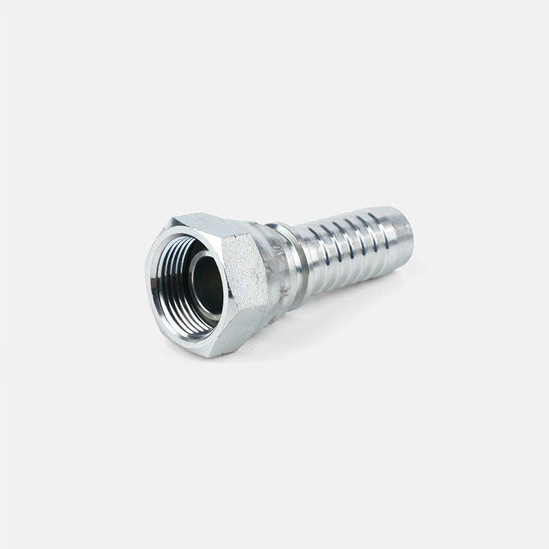
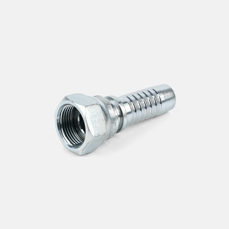
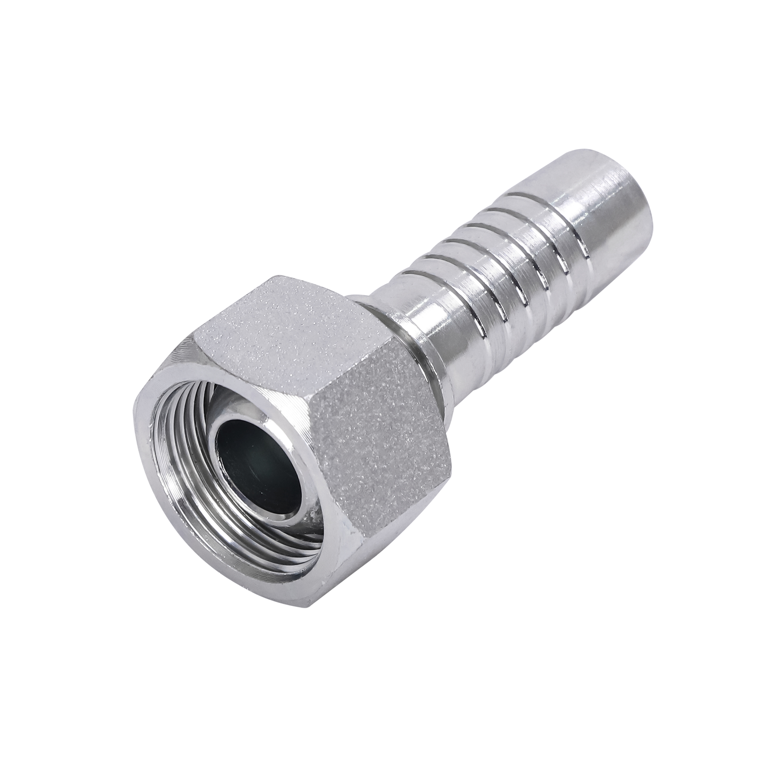
Hydrauliske slangefittings er metalendeforbindelser, adaptere og koblinger, der forbinder en hydraulikslange med en pumpe, cylinder, ventil, filter eller en anden slange. De udfører tre opgaver på én gang: De fastgør fysisk slangen til resten af systemet, de skaber en tryktæt forsegling, så væske ikke kan slippe ud, og i mange tilfælde giver de en tekniker mulighed for at lede væske i en vinkel eller trin mellem forskellige størrelser.
Hver hydraulisk slangefitting er virkelig lavet af to halvdele, der skal matche: krympnings- eller fastgørelsesenden, der griber selve slangen, og forbindelsesenden, der passer til porten, ventilen eller modstående fitting. At få krympeenden forkert betyder, at slangen kan blæse af under tryk. At få forbindelsesenden forkert betyder, at samlingen vil lække, krydse gevind eller simpelthen aldrig passe sammen overhovedet.
De tre dele, hver tilpasningsidentifikation afhænger af
- Trådtype: mønsteret skåret ind i metallet, såsom NPT, JIC, BSPP eller metrisk, som bestemmer, hvordan fittings skruer sammen.
- Sæde stil: den indvendige form, der faktisk skaber tætningen, såsom en 37 graders flare, en O-ringflade eller et tilspidset rørgevind, der tætner på selve gevindene.
- Størrelse: den nominelle størrelseskode, ofte skrevet som et stregnummer, såsom bindestreg 6 eller bindestreg 8, med henvisning til slangens indvendige diameter i sekstendedele af en tomme.
Det hjælper at huske, at trådtype og sædestil er uafhængige variabler, selvom de ofte er bundtet sammen i en afslappet samtale. To fittings kan dele nøjagtigt det samme gevindmønster og udvendig diameter, mens de forsegler på helt forskellige måder, hvilket netop er grunden til, at måling af gevindet alene ikke altid er nok til at afslutte en identifikation. En lige gevindfitting kan for eksempel tætne med en bundet skive, en O-ring på en flade eller en O-ring i en rille på skaftet, og hver af disse kræver en anden parringsdel, selvom gevindene i sig selv ville skrue fint sammen.
Det er også her, en masse forfalskede eller uoverensstemmende eftermarkedsdele giver problemer. Et beslag, der ser korrekt ud og skrues glat på, kan stadig være helt forkert sædestil, hvilket enten forhindrer en ordentlig tætning i at dannes eller i værste fald tillader forbindelsen at blive strammet nok til at virke sikker, mens den stadig lækker gradvist under tryk.
Hydrauliske fittingstyper forklaret
Når folk spørger om hydrauliske fittingstyper, stiller de normalt to forskellige spørgsmål på én gang: hvilken form er fittingen, og hvilken gevind- eller tætningsstandard bruger den. Begge dele har betydning, og en korrekt identifikation kræver begge svar.
Efter form og funktion
| Passende form | Hvad det gør | Almindelig brug |
|---|---|---|
| Lige adapter | Forbinder to porte eller slangeender i en direkte linje | Pumpe til slange tilslutning |
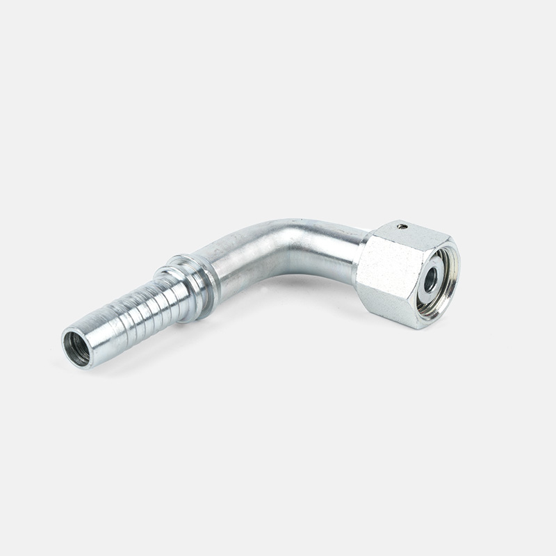
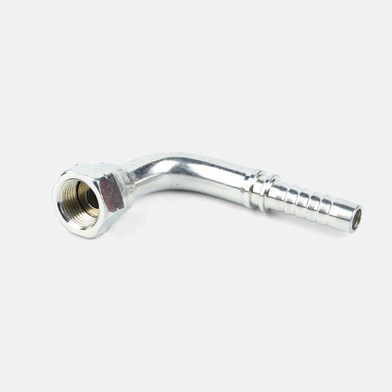
| 90 graders albue | Ændrer retning med en ret vinkel for at spare plads | Tætte cylinderporte på gravemaskiner |
| 45 graders albue | Skifter retning gradvist med mindre flowbegrænsning | Ventilbank routing |
| T-shirt montering | Splitter eller sammenføjninger flyder ind i en tredje linje | Tilførsel af to kredsløb fra én pumpeledning |
| Krydspasning | Split flyder i tre yderligere retninger | Manifoldblokke med flere målere |
| Reducer eller expander | Trin mellem to forskellige slangestørrelser | Tilslutning af en dash 8-slange til en dash 6-port |
| Drejelig adapter | Tillader rotation uden at sno slangen | Slanger, der bøjer under udstyrs bevægelse |
| Hætte og stik | Forsegler en ubrugt port fuldstændigt | Blokerer et ekstra pumpeudtag |
Efter gevind og forsegling Standard
Det er den kategori, der skaber mest forvirring, fordi flere trådstandarder ser næsten identiske ud med det utrænede øje. Tabellen nedenfor er den hurtigste måde at indsnævre, hvad du holder.
| Standard | Forseglingsmetode | Trådvinkel | Visuel ledetråd |
|---|---|---|---|
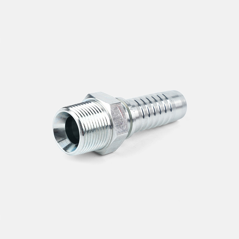
| NPT (National Pipe Tapered) | Tætner på koniske gevind, ofte med tætningsmiddel | 60 grader, tilspidset | Tråde er synligt smalle mod spidsen |
| NPSM (lige) | Tætner med en skive eller O-ring, lige gevind | 60 grader, lige | Tråde forbliver i samme bredde langs skaftet |
| JIC 37 grader | Forsegler på en 37 graders flare kegle | 37 graders blus | Synligt kegleformet sæde inde i beslaget |
| SAE 45 graders Flare | Forsegler på en 45 graders flare kegle | 45 graders blus | Lavere flare vinkel end JIC |
| ORFS (O-Ring Face Seal) | Tætner med en O-ring på en flad flade | Lige tråd, fladt ansigt | Synlig gummi O-ring rille på en flad flade |
| BSPP (British Parallel) | Tætner med en bundet skive, lige gevind | 55 grader, lige | Afrundet trådkamme, ofte stemplet med et G |
| BSPT (British Tapered) | Tætninger på koniske gevind | 55 grader, tilspidset | Svarende til NPT, men rundere gevindprofil |
| Metrisk DIN | Forsegler med en fanget O-ring eller bidering | 60 grader, lige or tapered variants | Størrelse stemplet i millimeter, ikke tommer |
Almindelig fejl NPT- og BSPT-tråde ser næsten identiske ud og vil ofte begynde at tråde sammen og derefter binde eller lække, når de er strammet. Bekræft altid med en gevindstigningsmåler, før du antager en match, især på importeret udstyr, hvor BSPP og BSPT er almindelige.
AN Hydraulikfittings forklaret
AN hydrauliske fittings, nogle gange søgt som en hydraulisk fittings, tager deres navn fra Army Navy specifikation oprindeligt udviklet til flybrændstof og hydrauliske linjer. De er siden blevet almindelige i ydeevne biler, motorsport og nogle mobile hydrauliske applikationer på grund af deres stærke 37 graders flare tætning og pålidelige genanvendelige design.
En AN-fitting tætner ved hjælp af en 37 graders flare, som mekanisk er den samme sædevinkel som en JIC-fitting. Faktisk er AN- og JIC-fittings af samme stregstørrelse normalt udskiftelige, hvilket er en af grundene til, at folk ofte blander de to navne sammen. Den reelle forskel er for det meste i mærkningskonventionen og gevindklassen frem for selve tætningsgeometrien.
Sådan fungerer AN Sizing
AN-fittings dimensioneres ved hjælp af et streg-talsystem, hvor tallet refererer til rørets udvendige diameter i sekstendedele af en tomme. Et bindestreg 6 AN fitting er seks sekstendedele af en tomme, hvilket er tre ottendedele af en tomme. Et streg 8 er otte sekstendedele eller en halv tomme. Dette er den samme nummereringslogik, der bruges til JIC-fittings, hvilket er en anden grund til, at de to familier så ofte forveksles i marken.
| AN Dash Størrelse | Rør udvendig diameter | Typisk brug |
|---|---|---|
| Dash 4 | Kvart tomme | Målerledninger, små brændstofledninger |
| Dash 6 | Tre ottendedele tomme | Brændstofforsyning, små hydrauliske kredsløb |
| Dash 8 | Halv tomme | Servostyring, mellemtryks hydrauliske ledninger |
| Dash 10 | Fem ottendedele tomme | Større hydrauliske kredsløb, oliekølere |
| Dash 12 | Tre kvart tomme | Højt flow hydraulik- og transmissionsledninger |
Identifikationstip Kig efter blusvinklen først. En ægte AN- eller JIC-fitting har et synligt 37 graders kegleformet sæde inde i fittingen. Hvis sædet er fladt med en O-ringsrille i stedet, ser du på en ORFS-fitting, ikke en AN-fitting, selvom gevindstørrelsen ligner.
Monteringsmaterialer og plettering som identifikationsspor
Metallet en fitting er lavet af, og pletteringen på dens overflade, kan indsnævre dens identitet, før du overhovedet tager en skydelære op. De fleste hydrauliske fittings er fremstillet af kulstofstål, rustfrit stål eller messing, og hvert materiale har en tendens til at dukke op på forudsigelige steder i et system.
| Materiale | Typisk udseende | Hvor du finder det |
|---|---|---|
| Forzinket kulstofstål | Lys sølv til let gul finish | Standard mobile hydraulikslangefittings og adaptere |
| Forkromet stål | Meget reflekterende, spejllignende finish | Bil- og udseendefokuserede hydrauliske linjer |
| Rustfrit stål | Matt matgrå, modstår korrosion, ikke magnetisk i nogle kvaliteter | Fødevarekvalitet, marine eller ætsende væskesystemer |
| Messing | Gulguld tone, blødere metal | Lavtryksluft og lette hydrauliske ledninger, målere |
| Sort oxid stål | Mat sort finish | Nejgle pumpeporte og industrielle ventilblokke |
Plettering og uædle metal fortæller dig ikke trådstandarden i sig selv, men de indsnævrer den sandsynlige anvendelse hurtigt. Et messingbeslag på en højtrykscylinderledning er for eksempel usædvanligt og værd at dobbelttjekke, da messing generelt er forbeholdt kredsløb med lavere tryk. Et rustfrit fitting, der optræder i et ellers helt stålsystem, signalerer ofte en ætsende væske eller en reservedel af marinekvalitet, hvilket er et nyttigt fingerpeg, når man skal spore tilbage til den korrekte gevindfamilie og trykklassificering.
Hurtigt tjek Kør en lille magnet nær beslaget. Kulstofstål og de fleste rustfrie kvaliteter, der bruges i strukturelle fittings, vil reagere anderledes på en magnet end austenitisk rustfrit, hvilket giver dig en hurtig grov sortering, før enhver måling begynder.
Værktøj du skal bruge for at identificere hydrauliske fittings
Korrekt identifikation afhænger langt mere af at have de rigtige værktøjer end af at huske hver standard. Et lille sæt, der opbevares i en butiksskuffe eller en servicelastbil, vil løse det store flertal af identifikationsspørgsmål på under et minut.
Digital skydelære
Måler udvendig diameter af hangevind og indvendig diameter af hunporte nøjagtigt til en hundrededel af en millimeter eller tusindedel af en tomme, hvilket er afgørende for at adskille tætte gevindstørrelser.
Gevindstigningsmåler
Et foldesæt af tynde blade skåret med forskellige trådmønstre. At matche en klinge mod fittingen bekræfter gevind pr. tomme eller millimeter stigning på få sekunder.
Sædevinkelmåler
Et simpelt værktøj i vinkelmålerstil eller trykt skabelon, der bruges til at bekræfte, om et flaresæde er skåret ved 37 grader eller 45 grader, da de to ser meget tæt på alene med øjet.
Tilpasningsidentifikationsskema
Et trykt eller lamineret diagram, der krydshenviser udvendig diameter og tråd, tæller i forhold til alle almindelige standarder, ideelt set ved siden af kaliberen til øjeblikkelig reference.
Stålbørste og rengøringsmiddel
Fjerner snavs, gammelt tætningsmiddel og korrosion, så gevind og stemplede varenumre faktisk er læselige, før du måler noget.
Reference prøvebeslag
Et lille mærket sæt kendte gode beslag i butikken, brugt til at sammenligne en ukendt del med en bekræftet kendt standard side om side.
Hydrauliske pumpefittings
Hydrauliske pumpefittings er konnektorerne, der er monteret direkte på pumpens indløbs- og udløbsporte, sammen med husets dræningsport på mange gear- og stempelpumper. Disse er nogle af de højeste spændingsforbindelsespunkter i hele systemet, fordi pumpen genererer det tryk, som alt nedstrøms skal modstå.
Pumpeproducenter specificerer typisk en af en lille håndfuld portgevindstandarder, oftest SAE lige gevind O-ringporte, NPT tilspidsede porte eller metriske porte på europæiske byggede pumper. At identificere porten korrekt før bestilling af en fitting forhindrer en meget almindelig og dyr fejl: at tvinge en tilspidset NPT-fitting ind i en lige SAE O-ringsport, som kan knække pumpehuset.
Trykklassificeringsforskelle på tværs af porte på den samme pumpe er også værd at forstå for identifikationsformål. En tandhjulspumpe designet til et arbejdstryk på omkring 3.000 psi ved udløbet kan have en indløbsport, der kun er normeret til et par psi vakuummodstand, og et husdræn vurderet et godt stykke under det. Det er ikke forkert at montere en højtrykskonnektor på kabinettets afløb, men at installere en underdimensioneret eller lav kvalitet fitting på udløbsporten er en af de mere almindelige årsager til tidlig pumpefittingsfejl i marken, da denne forbindelse ser fuldt systemtryk og eventuelle trykspidser fra cylinder- eller ventilchok.
Mange producenter af mobilt udstyr standardiserer på SAE lige gevind O-ring udspringsporte på tværs af en hel produktlinje, specifikt fordi de tætner pålideligt ved en bred vifte af tryk uden at være afhængig af gevindforsegling. Når man udskifter en fitting på denne porttype, er selve O-ringen normalt den første ting, man skal inspicere, da en hærdet, fladtrykt eller manglende O-ring er en langt mere almindelig årsag til en pumpefittings lækage end et virkelig forkert gevind.
Sådan identificeres en pumpeport
- Se efter en synlig O-ringsrille, der er bearbejdet i portfladen eller skulderen. Hvis det er til stede, er dette næsten altid en SAE lige gevindport, ikke NPT.
- Mål gevindet med en skydelære på tværs af den udvendige diameter, og kontroller derefter gevindtal pr. tomme med en gevindstigningsmåler.
- Tjek om trådene tilspidser mod åbningen. En synlig tilspidsning antyder kraftigt NPT eller BSPT frem for en lige gevindport.
- Krydshenviser pumpeproducentens portdiagram ved hjælp af pumpens modelnummer, da de fleste producenter offentliggør nøjagtige portspecifikationer for hver model.
1
Indløbsport
Normalt den største port på pumpen, der fører væske ind fra reservoiret ved lavt tryk. Ofte størrelse større end udløbet for at reducere kavitationsrisiko.
2
Udløbsport
Fører tryksat væske nedstrøms til ventiler og aktuatorer. Denne port og dens montering ser det højeste arbejdstryk i pumpen.
3
Case Afløbsport
En mindre lavtryksport, der leder intern lækage tilbage til reservoiret. At forveksle dette med en trykport er en hyppig og kostbar fejl.
Hydraulikslangetyper Oversigt
At kende hydraulikslangetyper er vigtige for identifikation, fordi slangekonstruktionen påvirker, hvilke fittings der sikkert kan krympes eller fastgøres til den. Slanger er generelt klassificeret efter deres forstærkningslag og trykklassificering, efter standarder som SAE 100R.
| Slangetype | Forstærkning | Typisk trykområde | Fælles ansøgning |
|---|---|---|---|
| SAE 100R1 | Enkelt flettet ståltråd | Op til 3.000 psi | Returledninger, lavtrykskredsløb |
| SAE 100R2 | Dobbelt flettet ståltråd | Op til 5.000 psi | Generel mobil hydraulik |
| SAE 100R12 | Fire spiraltrådslag | Op til 4.000 psi ved større boring | Højt flow hydrauliske kredsløb |
| SAE 100R13 | Fire til seks spiraltrådslag | Op til 6.000 psi | Tungt bygge- og mineudstyr |
| Termoplastisk slange | Syntetisk fiber fletning | Op til 3.000 psi | Letvægts, kemikalieresistente applikationer |
| PTFE foret slange | Rustfrit stål braid over PTFE core | Varierer efter konstruktion | Høj temperatur eller aggressive væsker |
Fittingen, der er fastgjort til en slange, skal ikke kun matche portgevindet i den anden ende, men også selve slangekonstruktionen, da en lettere fitting, der er krympet på en tung spiraltrådsslange, kan glide af under tryk, selvom den skrues perfekt på i den anden ende.
Slange endefittings
Slangeendefittings er de specifikke tilslutninger permanent fastgjort til slangen, i modsætning til løse adaptere, der blot skrues mellem to fittings. Der er tre hovedfastgørelsesmetoder, der bruges til at forbinde en slangeendebeslag til selve slangen.
Vedhæftningsmetoder
| Metode | Hvordan det virker | Genanvendelig | Typisk indstilling |
|---|---|---|---|
| Krympet (permanent) | En crimpemaskine komprimerer en metalmuffe rundt om slangen og fittingen | No | Fabriks- og butiksproduktion, mest almindelig metode |
| Feltet kan monteres | Montering af skruer eller klemmer på slangen uden specialmaskineri | Nogle gange | Nødreparationer, fjernarbejdspladser |
| Genanvendelig screw type | Monteringskomponenter skrues sammen rundt om slangeenden | Ja | Ældre udstyr, lavvolumenværksteder |
Når du identificerer en slangeendefitting på en eksisterende enhed, skal du kontrollere ferrulen, som er den ydre metalmuffe. Beslagets mønster, uanset om det har skåret eller uskåret konstruktion, sammen med enhver producents stempling, peger normalt direkte på det korrekte reservedelsnummer uden at skulle måle fra bunden.
Hvorfor dette betyder noget De fleste fabrikanter af slange og fittings stempler et varenummer eller en størrelseskode direkte på ferrul eller fittingsekskant. Før du måler noget, skal du kontrollere for stemplede markeringer, da dette alene ofte bekræfter den nøjagtige identifikation på få sekunder.
Hydraulikslangeforbindelsestyper sammenlignet
Hydraulikslangeforbindelsestyper beskriver, hvordan to separate linjer eller komponenter forbindes, hvilket er et lidt anderledes spørgsmål end gevindstandard alene. Nedenfor er en praktisk sammenligning af de stikstile, du oftest støder på.
| Connector Type | Forseglingsplacering | Styrker | Hold øje med |
|---|---|---|---|
| Flare-stik (JIC eller AN) | Metal til metal kegletætning | Stærk, bredt tilgængelig, genbrugelig | Kan blive beskadiget ved overspænding eller gentagne afbrændinger |
| O-ring ansigtstætning (ORFS) | O-ring komprimeret mod en flad flade | Fremragende lækagemodstand, højtryksklassificeret | O-ring skal udskiftes, hvis den genbruges, genbrug aldrig en beskadiget |
| NPT gevindstik | Tilspidset trådinterferens | Enkel, billig, bredt lagerført | Tilbøjelig til lækager, hvis den bliver over- eller underspændt |
| Flangeforbindelser (SAE-kode 61 og kode 62) | O-ring eller pakning mellem to flade flanger fastgjort med bolte | Klarer meget højt tryk og store borestørrelser godt | Kræver korrekt boltmomentmønster for at tætne korrekt |
| Hurtig afbrydelse af koblinger | Indvendig tallerkenventil med O-ringstætninger | Hurtig til- og frakobling uden værktøj | Højere tryktab end et fast stik |
| Knast- og rilleforbindelser | Pakning komprimeret af en låsearmsmekanisme | Meget hurtig at tilslutte, almindelig på overførselsslanger | Generelt lavere tryk end andre typer |
Metriske versus kejserlige fittings: Hurtig identifikation
Udstyr bygget i Nordamerika bruger generelt kejserlige gevindstandarder såsom NPT, JIC og SAE lige gevind porte, mens udstyr bygget i Europa og store dele af Asien ofte bruger metriske gevind efter DIN eller ISO specifikationer. Blandede flåder, importeret maskineri og eftermarkedsdele betyder, at begge kan dukke op på den samme arbejdsplads, så en hurtig måde at sortere den ene fra den anden sparer en masse spildte målinger.
| Clue | Foreslår Imperial | Foreslår metrisk |
|---|---|---|
| Fabrikantens oprindelse | Nordamerikansk mærke eller udstyr | europæisk eller asiatisk mærke eller udstyr |
| Målt diameter | Falder tæt på en brøkdel af en tomme, såsom tre ottendedele eller en halv tomme | Falder tæt på et rundt millimeter tal såsom 14 eller 18 millimeter |
| Stemplet markering | Størrelse stemplet som bindestregnummer eller brøk | Størrelse stemplet direkte i millimeter, ofte med et M-præfiks |
| Gevindkammens form | Skarpere 60 graders profil almindelig på NPT og JIC | Ofte en afrundet kam på DIN og nogle ISO varianter |
Når en målemarkøraflæsning falder mellem to standard kejserlige brøker, men er tæt på linje med en rund metrisk figur, er denne uoverensstemmelse som regel det tydeligste tegn på, at du faktisk har en metrisk tilpasning i stedet for en slidt eller mærkelig størrelse imperial. Konvertering af aflæsningen til millimeter før sammenligning med et diagram undgår en masse spildtid på at forsøge at tvinge en kejserlig kamp, der aldrig var der.
Eksempler på identifikation af den virkelige verden
Gennemarbejdelse af nogle få konkrete scenarier gør tjeklisten lettere at anvende under virkelige forhold.
Eksempel 1: Gravemaskinebomcylinderlinje
En tekniker trækker en utæt beslag fra en gravemaskinebomcylinder. Sædet har en synlig kegleform, den udvendige diameter måler tæt på en og en sekstende tomme, og en gevindstigningsmåler bekræfter 12 gevind pr. tomme. Krydshenvisninger af et JIC-størrelsesdiagram identificerer dette som en 12 JIC 37 graders fitting med bindestreg, hvilket er i overensstemmelse med kravene til høj flow og højtryk i et bomcylinderkredsløb.
Eksempel to: Importeret pumpeindløbsport
En erstatningspumpe fra en europæisk leverandør har en port, der ikke accepterer en standard NPT-fitting, der bindes efter kun en omgang eller to. Måling af den udvendige diameter giver en aflæsning tæt på 33 millimeter i stedet for en ren kejserbrøk, og gevindene har en mærkbart rundere kam. Dette peger på en metrisk DIN-port i stedet for NPT, og bestilling af en metrisk adapter løser uoverensstemmelsen.
Eksempel tre: Utæt slangeende efter en nylig reparation
En slange samlet en uge tidligere begynder at sive væske ved forbindelsen til en ventilblok. Beslaget er en ORFS-stil med en flad flade og O-ringsrille, og inspektion viser, at O-ringen er flad og let skåret. I stedet for en gevinduoverensstemmelse peger dette direkte på en beskadiget eller genbrugt O-ring som årsagen, hvilket bekræfter, at ikke hver lækage kan spores tilbage til en identifikationsfejl.
En trinvis metode til at identificere enhver hydraulisk fitting
Med alle ovenstående kategorier i tankerne er her en gentagelig proces, der fungerer, uanset om du er i en butik, et lager eller ude på en arbejdsplads med en ødelagt slange i hånden.
- Rengør beslaget, så gevind, sæde og eventuelle prægede markeringer er fuldt synlige.
- Tjek efter et producentstempel eller et reservedelsnummer på den sekskantede krop eller ferrule, før du gør noget andet.
- Se på sædet: en kegleform antyder en flare fitting, en flad flade med en O-ringsrille antyder ORFS, og et almindeligt tilspidset gevind uden separat sæde antyder NPT eller BSPT.
- Mål den udvendige diameter af hangevindet med en skydelære.
- Tæl gevindene pr. tomme ved hjælp af en gevindstigningsmåler, eller mål gevindafstanden i millimeter, hvis det ser ud til at være en metrisk tilpasning.
- Kontroller, om gevindene er parallelle langs skaftet eller synligt tilspidser mod spidsen.
- Krydsreference den udvendige diameter og gevindantal i forhold til et offentliggjort hydraulisk fittings-størrelsesdiagram for at bekræfte den nøjagtige standard- og stregstørrelse.
- Bekræft tilpasningen med en matchende gevindmåler, før du krymper eller installerer en ny slangesamling.
Praktisk eksempel Et fitting, der måler ni sekstendedele af en tomme på tværs af gevindene med 18 gevind pr. tomme og et synligt 37 graders keglesæde, er næsten helt sikkert en dash 6 JIC eller AN fitting. Den samme udvendige diameter med en flad flade og O-ringsrille ville i stedet pege på en streg 6 ORFS fitting i stedet for en flare stil konnektor.
Hvor længe holder hydraulikslanger
Hvor længe holder hydraulikslanger er et af de mest almindelige spørgsmål, der stilles ved siden af monteringsidentifikation, da en slange og dens fittings normalt udskiftes sammen. Under normale arbejdsforhold holder en korrekt installeret hydraulikslange typisk mellem to og fem år, selvom mange industriretningslinjer anbefaler udskiftning eller grundig inspektion hvert andet år uanset synlig tilstand, da indvendigt slid ikke altid er synligt udefra.
Holdbarheden før installation har også betydning og bliver nogle gange overset. En slange, der opbevares korrekt, væk fra direkte sollys, ozonkilder og ekstreme temperaturudsving, kan stå ubrugt i flere år og stadig fungere efter dens nominelle specifikation, når den først er installeret. En slange, der opbevares forkert, kan dog nedbrydes, før den nogensinde ser en enkelt driftscyklus, hvilket er grunden til, at mange producenter stempler en fremstillingsdato direkte på slangedækslet til sporingsformål.
Duty cycle spiller også en stor rolle, som er let at undervurdere. En slange på et stykke udstyr, der løber kontinuerligt gennem flere skift om dagen, vil typisk nå slutningen af sin praktiske levetid hurtigere end en identisk slange på udstyr, der kun bruges få timer om ugen, selvom begge kan have samme trykklassificering og være bygget af samme konstruktion.
| Faktor | Effekt på slangens levetid |
|---|---|
| Driftstryk i forhold til rating | At køre konsekvent nær det maksimale nominelle tryk forkorter levetiden mærkbart |
| Temperatureksponering | Ekstrem varme nedbryder det indre rør hurtigere, hvilket ofte reducerer den forventede levetid betydeligt |
| Bøjningsradius | Bøjning af en slange strammere end dens nominelle minimumsradius forårsager tidlig ledningsarmeringstræthed |
| Væskekompatibilitet | Brug af en væske, som inderrøret ikke er designet til, kan forårsage hævelse eller revner inden for måneder |
| Slid og gnidning | Konstant kontakt med rammer eller andre slanger slider gennem det ydre dæksel og blotlægger forstærkningen |
| UV- og ozoneksponering | Udendørs udstyr efterladt i direkte sol ser hurtigere dæk revner end indendørs udstyr |
Advarselsskilte, at en slange eller fitting skal udskiftes
- Synlige revner, blærer eller bløde pletter på yderbeklædningen.
- Enhver vådhed, oliefilm eller udsivning ved monteringsforbindelsespunktet.
- Korrosion eller gruber på fittingkroppen eller ferrul.
- Knæk eller udfladning overalt langs slangens længde.
- Frilagt trådforstærkning, der viser gennem et slidt dæksel.
- Et beslag, der er blevet fjernet og geninstalleret flere gange, da gentagen tilspænding kan slide sædet.
Sikkerhedsbemærkning En lækage i en højtrykshydraulikledning kan injicere væske under huden uden et tydeligt sprøjtemønster, hvilket er en alvorlig medicinsk nødsituation, selvom lækagen ser mindre ud. Enhver formodet pinhole-lækage bør behandles som en nedluknings- og inspektionssituation, ikke noget, der skal kontrolleres med bare hånd.
Vedligeholdelsestips til at forlænge montering og slangelevetid
Korrekt identifikation er vigtigst på tidspunktet for installation eller reparation, men gode vedligeholdelsesvaner er det, der sørger for, at en korrekt identificeret montering fungerer godt i årevis frem for måneder. De fleste af de følgende fremgangsmåder koster lidt ud over lidt rutinemæssig opmærksomhed, men de forhindrer de fleste undgåelige hydrauliske forbindelsesfejl set i marken.
- Inspicer slangesamlinger efter en fast tidsplan i stedet for at vente på en synlig fejl, da intern ledningstræthed ikke altid viser ydre symptomer tidligt.
- Spænd fittings til det drejningsmoment, der er angivet af producenten, snarere end efter følelse, da overspænding af en flare eller ORFS fitting kan forvrænge sædet og forårsage en lækage.
- Støt lange slangeløb, så deres egen vægt ikke trækker i fittingforbindelsen ved pumpen eller cylinderporten.
- Hold udskiftnings-O-ringe ved hånden til ORFS- og SAE-fittings med lige gevind, da genbrug af en slidt O-ring er en af de mest almindelige årsager til en langsom lækage efter en reparation.
- Før slanger væk fra udstødningsmanifolder, skarpe kanter og bevægelige komponenter, hvor end udstyrets layout tillader det.
- Før en skriftlig registrering af gevindtype og stregstørrelse for hver slangeposition på en maskine, så en udskiftning kan bestilles uden at måle fra bunden hver gang.
- Rengør beslag før opbevaring og påfør en let beskyttende belægning på reservedele, der opbevares i en butik, da korrosion på ubrugte beslag kan gøre senere identifikation og montering mærkbart sværere.
- Træn mere end én person på identifikationstjeklisten, der er dækket af denne vejledning, så korrekt valg af tilpasning ikke afhænger af, at en enkelt person er tilgængelig under et sammenbrud.
Standardhuse bag hydrauliske monteringsspecifikationer
De fleste af gevind- og tætningsstandarderne, der er dækket i denne vejledning, kan spores tilbage til et lille antal organisationer, og at vide, hvilket organ der styrer en given standard, kan hjælpe, når du sporer et officielt diagram eller specifikationsark.
| Organisation | Standarder det udgiver | Relevans for identifikation |
|---|---|---|
| SAE International | SAE-porte med lige gevind, SAE 100R-slangespecifikationer, flangekoder | Styrer de fleste nordamerikanske mobile hydrauliske gevind- og slangestandarder |
| ISO | Metriske monteringsdimensioner, generelle standarder for hydrauliske komponenter | Fælles referencepunkt for udstyr bygget efter internationale specifikationer |
| DIN | Tysk metrisk fitting og portmål | Findes ofte på europæisk fremstillede pumper og ventiler |
| ANSI | NPT rørgevinddimensioner | Definerer standarden for koniske rørgevind, der bruges på tværs af mange industrier ud over hydraulik |
Ingen af disse organisationer kræver særlig adgang til reference, og de fleste udgiver i det mindste opsummerende dimensionstabeller, der er frit tilgængelige, hvilket gør det muligt at bekræfte en identifikation mod en autoritativ kilde i stedet for kun at stole på et butikskort af ukendt oprindelse.
Ofte stillede spørgsmål
Hvad er den hurtigste måde at skelne NPT- og BSPT-tråde fra hinanden
Mål gevindstigningen med en måler og sammenlign den med et offentliggjort diagram. NPT bruger en 60 graders gevindvinkel, mens BSPT bruger 55 grader, men den visuelle forskel er subtil nok til, at en gevindmåler eller en direkte sammenligning med en kendt prøve er langt mere pålidelig end at se på den.
Er AN- og JIC-fittings virkelig udskiftelige
I de fleste praktiske tilfælde, ja, da begge bruger et 37 graders flare sæde og den samme tankestregstørrelseslogik. Nogle AN-fittings bruger en finere gevindklasse end kommercielle JIC-dele, så ved kritiske applikationer er det stadig værd at bekræfte, at gevindstigningen matcher nøjagtigt, før man antager fuld udskiftelighed.
Kan jeg blande hydrauliske fittings typer fra forskellige mærker
Ja, så længe trådstandarden, sædestilen og stregstørrelsen matcher nøjagtigt. Gevind- og sædestandarder såsom JIC, ORFS, NPT og BSPP er branchespecifikationer, ikke mærkespecifikke designs, så en korrekt identificeret fitting fra én producent vil passe korrekt med en matchende fitting fra en anden.
Hvordan identificerer jeg hydraulikpumpefittings uden en manual
Kontroller, om der er en synlig O-ringsrille ved porten, mål den udvendige diameter og gevindstigningen, og bemærk, om gevindet tilspidser. Kombineret med pumpens modelnummer stemplet på huset, kan de fleste producenter bekræfte portspecifikationen selv uden den originale manual i hånden.
Hvad er forskellen mellem en slangeendefitting og en adapterfitting
Et slangeendestykke er permanent fastgjort til selve slangen, typisk ved krympning. En adapterfitting er en separat løs komponent, der skrues mellem to andre fittings eller porte, ofte brugt til at gå mellem størrelser eller konvertere mellem gevindstandarder.
Hvor længe holder hydraulikslanger i udendørs udstyr specifikt
Udendørs udstyr udsat for konstant sol, temperatursvingninger og snavs har typisk en kortere levetid end indendørs maskiner, og lander ofte i den nedre ende af to til fem års rækkevidde. Regelmæssig inspektion betyder endnu mere i udendørs omgivelser, fordi UV-eksponering kan knække et dæksel i god tid, før intern ledningsarmering faktisk svigter.
Hvorfor lækker en fitting, selv efter at gevindtypen er korrekt identificeret
Korrekt gevindidentifikation bekræfter kun, at delene fysisk kan passe sammen. Utætheder efter en korrekt match er normalt forårsaget af en beskadiget eller genbrugt O-ring, en forbindelse med under eller for meget tilspændt drejningsmoment, en ridset eller hullet tætningsflade eller et flare sæde, der blev forvrænget under en tidligere installation.
Er det sikkert at blande metriske og imperiale fittings med en adapter
Ja, dedikerede metriske til imperiale adaptere er bredt tilgængelige og almindeligt anvendte, især på blandede flåder med udstyr hentet fra forskellige regioner. Nøglen bekræfter begge sider af adapteren uafhængigt, da en adapter i virkeligheden kun er to separate monteringsidentifikationer, der er samlet i én del.
Afsluttende tanker
At identificere en hydraulisk fitting korrekt kommer ned til en kort, gentagelig tjekliste: rengør den, se efter stemplede markeringer, undersøg sædeformen, mål gevindet med en skydelære og stigningsmåler, og bekræft i forhold til et offentliggjort diagram, før du bestiller eller krymper en erstatning. At forstå det bredere billede, fra hvad en hydraulikslange faktisk er, til forskellene mellem AN hydrauliske fittings, hydrauliske pumpefittings, slangeendefittings og de forskellige hydrauliske slangeforbindelsestyper, gør en gætteleg til en hurtig og sikker proces.
Parring af korrekt monteringsidentifikation med rutinemæssige inspektionsvaner, da hydraulikslanger generelt kræver opmærksomhed inden for to til fem års service, er den mest pålidelige måde at undgå uplanlagt nedetid, væskeindsprøjtningsskader og gentagne fejl på samme linje.

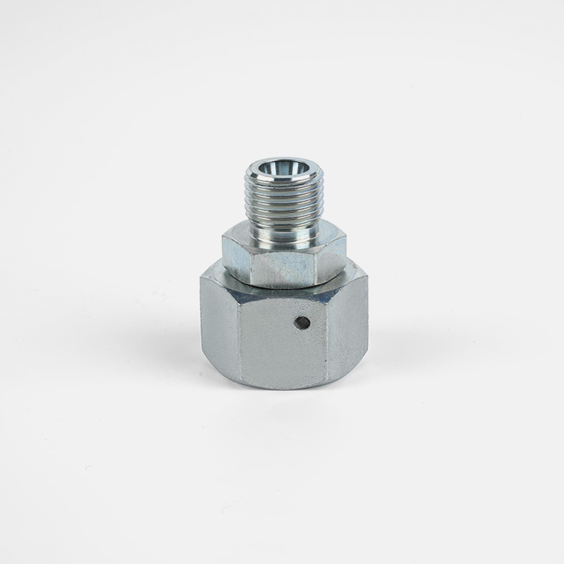
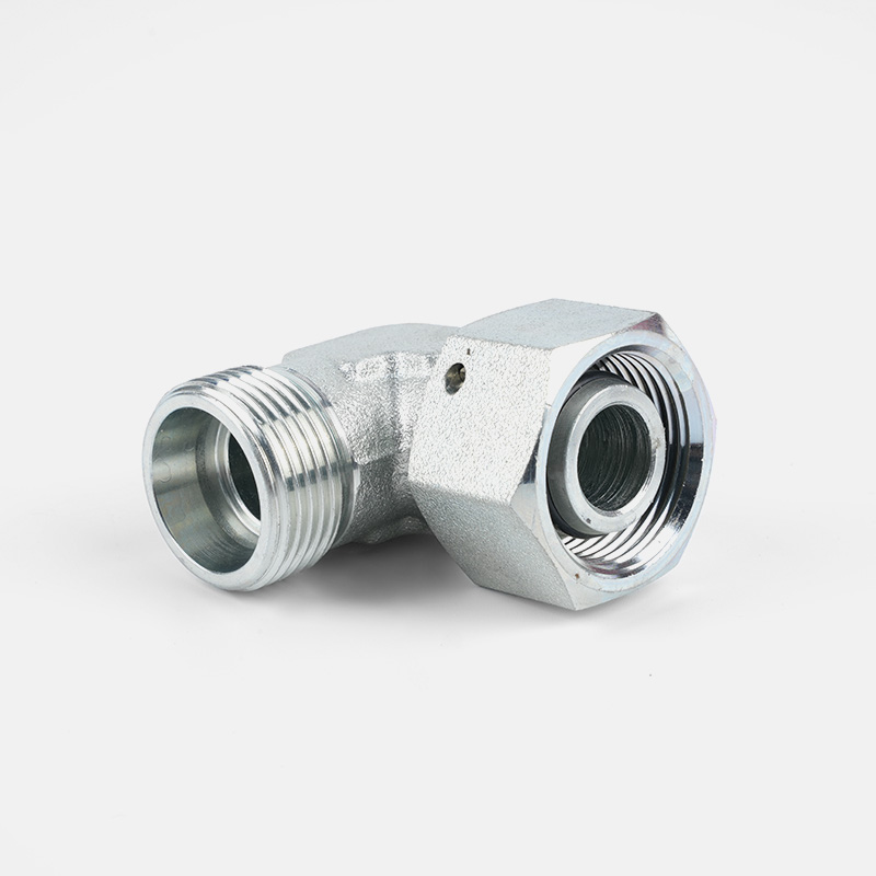
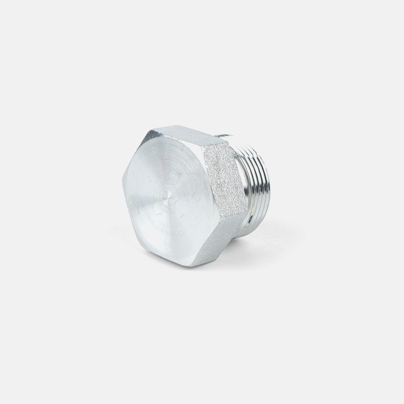
Brugerdefineret hydraulisk tilbehør
Fra koncept til produktion kan vi skabe de produkter, du ønsker
Produkter
Kontaktoplysninger
-

Tel: +86-159-6851-8588
-

E-mail: [email protected]
-

Add:Zhu Jia Station Village, Diankou Town, Zhuji City, Zhejiang-provinsen, Kina
Hurtigt link
Scan kode
Copyright © Zhejiang Tianxiang Machine Fittings Co.,Ltd.
